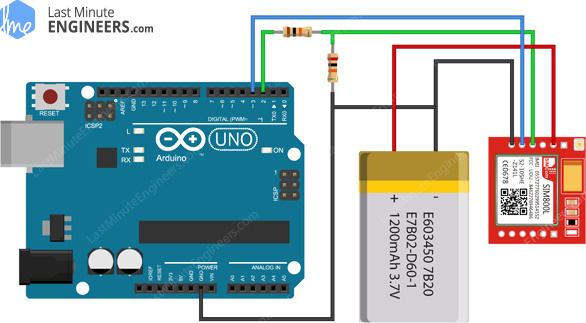
I have an Arduino UNO connected to a SIM800L. The SIM800L is connected to a 3.7v Battery and blinks once a second.
I am using this repository: https://github.com/HologramEducation/hologram-SIMCOM
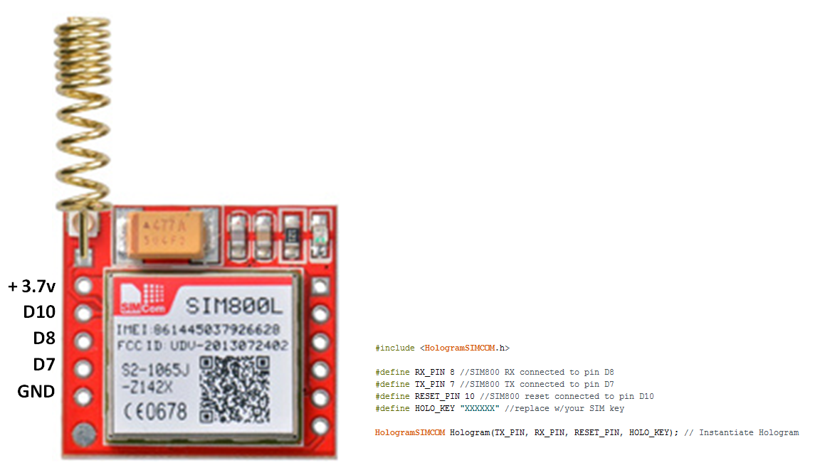
I opened the Kitchen Sink Example and added my device key and pin numbers to the header of the code. After compiling and uploading to the UNO, here is my result:
ERROR: Timeout when calling AT
| elapsed ms = 0
ERROR: begin() failed at AT
DEBUG: Verbose monitoring and modem serial access enabled
DEBUG: Write Modem Serial = AT+CGATT?
ERROR: Timeout when calling AT+CGATT?
| elapsed ms = 0
DEBUG: Write Modem Serial = AT+CIPSTATUS?
ERROR: Timeout when calling AT+CIPSTATUS?
| elapsed ms = 0
DEBUG: Write Modem Serial = AT+CIPMUX?
ERROR: Timeout when calling AT+CIPMUX?
| elapsed ms = 0
DEBUG: Write Modem Serial = AT+CIFSR
ERROR: Timeout when calling AT+CIFSR
| elapsed ms = 0
DEBUG: Write Modem Serial = AT+CSQ
ERROR: Timeout when calling AT+CSQ
| elapsed ms = 0
DEBUG: Write Modem Serial = AT+CIPSHUT
ERROR: Timeout when calling AT+CIPSHUT
| elapsed ms = 0
DEBUG: Write Modem Serial = AT+CSQ
ERROR: Timeout when calling AT+CSQ
| elapsed ms = 0
DEBUG: Write Modem Serial = AT+CGATT?
ERROR: Timeout when calling AT+CGATT?
| elapsed ms = 0
ERROR: failed at +CGATT
ERROR: unable to connect to cellular network
DEBUG: Write Modem Serial = AT+CGATT?
ERROR: Timeout when calling AT+CGATT?
| elapsed ms = 0
DEBUG: Write Modem Serial = AT+CIPSTATUS?
ERROR: Timeout when calling AT+CIPSTATUS?
| elapsed ms = 0
DEBUG: Write Modem Serial = AT+CIPMUX?
ERROR: Timeout when calling AT+CIPMUX?
| elapsed ms = 0
DEBUG: Write Modem Serial = AT+CIFSR
ERROR: Timeout when calling AT+CIFSR
| elapsed ms = 0
DEBUG: Write Modem Serial = AT+CSQ
ERROR: Timeout when calling AT+CSQ
| elapsed ms = 0
DEBUG: Write Modem Serial = AT+CIPSHUT
ERROR: Timeout when calling AT+CIPSHUT
| elapsed ms = 0
DEBUG: Write Modem Serial = AT+CSQ
ERROR: Timeout when calling AT+CSQ
| elapsed ms = 0
DEBUG: Write Modem Serial = AT+CGATT?
ERROR: Timeout when calling AT+CGATT?
| elapsed ms = 0
ERROR: failed at +CGATT
ERROR: unable to connect to cellular network
DEBUG: Write Modem Serial = AT+CIPSTART=1,“TCP”,“23.253.146.203”,“9999”
ERROR: Timeout when calling AT+CIPSTART=1,“TCP”,“23.253.146.203”,“9999”
| elapsed ms = 0
ERROR: failed to start TCP connection
DEBUG: Write Modem Serial = AT+CGATT?
ERROR: Timeout when calling AT+CGATT?
| elapsed ms = 0
DEBUG: Write Modem Serial = AT+CIPSTATUS?
ERROR: Timeout when calling AT+CIPSTATUS?
| elapsed ms = 0
DEBUG: Write Modem Serial = AT+CIPMUX?
ERROR: Timeout when calling AT+CIPMUX?
| elapsed ms = 0
DEBUG: Write Modem Serial = AT+CIFSR
ERROR: Timeout when calling AT+CIFSR
| elapsed ms = 0
DEBUG: Write Modem Serial = AT+CSQ
ERROR: Timeout when calling AT+CSQ
| elapsed ms = 0
DEBUG: Write Modem Serial = AT+CIPSHUT
ERROR: Timeout when calling AT+CIPSHUT
| elapsed ms = 0
DEBUG: Write Modem Serial = AT+CSQ
ERROR: Timeout when calling AT+CSQ
| elapsed ms = 0
DEBUG: Write Modem Serial = AT+CGATT?
ERROR: Timeout when calling AT+CGATT?
| elapsed ms = 0
ERROR: failed at +CGATT
ERROR: unable to connect to cellular network
DEBUG: Write Modem Serial = AT+CIPSTART=1,“TCP”,“23.253.146.203”,“9999”