Hi everyone. I’ve got a Dash V1.1 and I’m wondering if the schematics are available anywhere- I’ve gotten the schematics for V1.0 from github, but they are obviously different.
Specifically, I’m looking at the feasibility of powering the Dash from 3.3V. I understand this required a hardware mod in the Pro and V1.0 versions. With the correct schematic, I could probably work it out myself, but lacking that I’ll need some expert advice.
Thanks in advance,
Steve
PS: I’m sure you know, but there’s a LOT of broken links on the hologram site leading to the now-defunct konekt.io domain. It was frustrating until I realized I could in most cases replace the “konekt” with “hologram”, but it’s still a little annoying!
PPS: Great product- I’ve been playing with mine for a few days, already have plans for a remote weather station. Seems to be a great fit.
Hi Reuben- no worries on the delay, I’ve been a bit busy myself!
Definitely eager to see the new schematics- I’ve got some more questions about battery modes, specifically whether to use the onboard charger or supply my own (I want to use solar to power a remote site).
If I come across any more broken links, I’ll let you know, but lately it seems to be much better!
I’ve actually had pretty decent luck with 3.3 V or so. But as Erik has mentioned in another thread where I was kind of asking the same thing, it’s not the volts so much has the amps that will get you. It’s easy to find a 3.3 V source, but you’ll need at least 3 A when the modem needs it. That pretty much means it’s wise to use a battery of some sort, and then charge that.
I’ve done it two different ways: I connect directly to the battery port or the USB power pins on the USB connector (via a USB cable I sacrificed for the purpose). I was intrigued that the USB and battery connectors seem to operate in identical fashion; Erik responded that in fact they are identical as far as powering the board, and the jumper setting on the Dash 1.1 unit is used to turn on the battery charger. So, when powering from an extra power source, through either port, the recommendation is to leave the battery charger turned off (by leaving the jumper in the USB position).
I’ve actually had the Dash running well under 3 V, in fact down to 2.5 V (or slightly below). The problem at that level seems to be that the modem becomes distinctly unhappy, and wants to draw several amps when it’s in use. If you’re powering by a battery or a current limited source at that point, the current draw is enough to bring the voltage down well below 2 V instantly, which stopped the board.
[Edited 5/30/17 for grammar and spelling – I blame most of the errors on Siri!]
@ Michael.
Thanks, I tried the USB PIN (L1) and I got good results using 3.3V. I placed a 220uf capacitor in L1/L2 to handle UBlox’s high-current requirement and that somewhat works in my usecase. Will replace that with ultra capacitor in my next test.
I noticed there’s a 5V regulator near USB port so I tried 7.5 volts and it works just fine.
Lucky for me that all the sensor modules and all I2C/GPIO I’m working on are in the 3.3V rating so I don’t have any problem shifting the DASH to that voltage source.
Good info here, but I’m still a little confused. There’s a regulator by the USB but it’s 3.3V. There also seems to be a regulator onboard the MK22 user processor, input power on pin 8 (Vregin) and 3.3V out on pin 7 (Vout33). That output seems to be connected directly to the output of the discrete 3.3 regulator- in the schematics, there’s a bunch of 0-ohm “DNI” resistors which I’m assuming are “uninstalled jumpers” on board? It’s hard to determine what’s going where, because the layout of my physical board doesn’t match the schematic, and I’m not sure it the DNIs really open circuit and/or the non-DNI resistors are shorting resistors actually installed onboard.
Anyway, I’m guessing the user processor and the cell modem get their power from the “Vbatt” (i.e. unregulated USB/battery supply), and the 3.3V regulator (which is supplied from Vbatt/USB) supplies the “peripheral” circuits (serial interfaces, reset buttons, etc).
If that’s the case, feeding with 3.3 might work (well, considering the evidence, it does work lol), but there will be a drop for the aforementioned peripheral circuits- although maybe not enough to cause problems. Until the modem kicks in, but that’s another story!
Well, it’s back to the bench- here’s to hoping I don’t release the magic smoke…
Thanks for the Schematic!!!
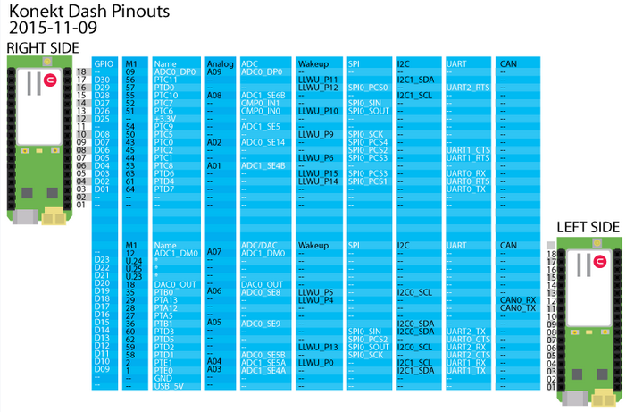
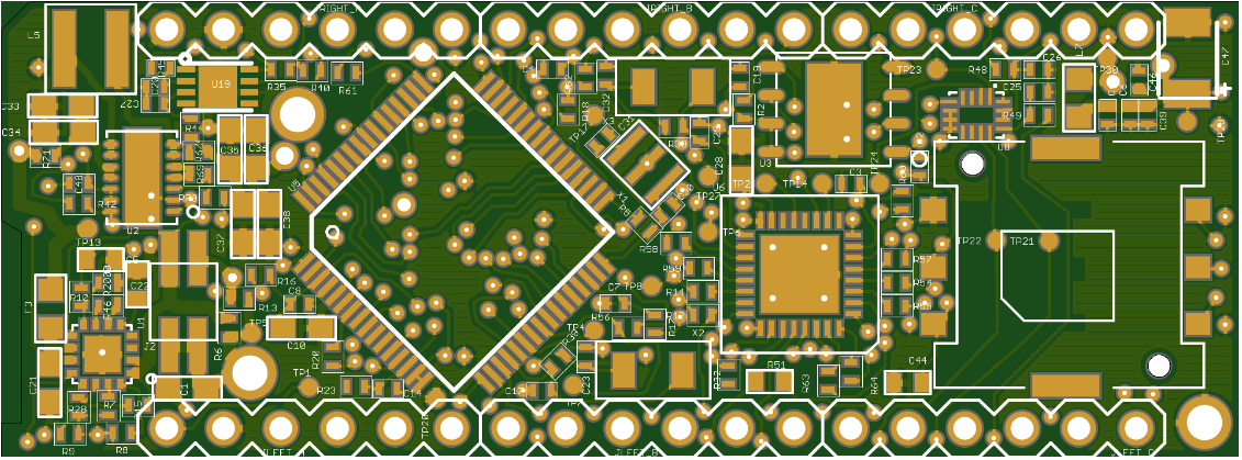
Now I know there’s JTAG for boundary scanning… but can you help me identify the pins and test points as identified in the document:
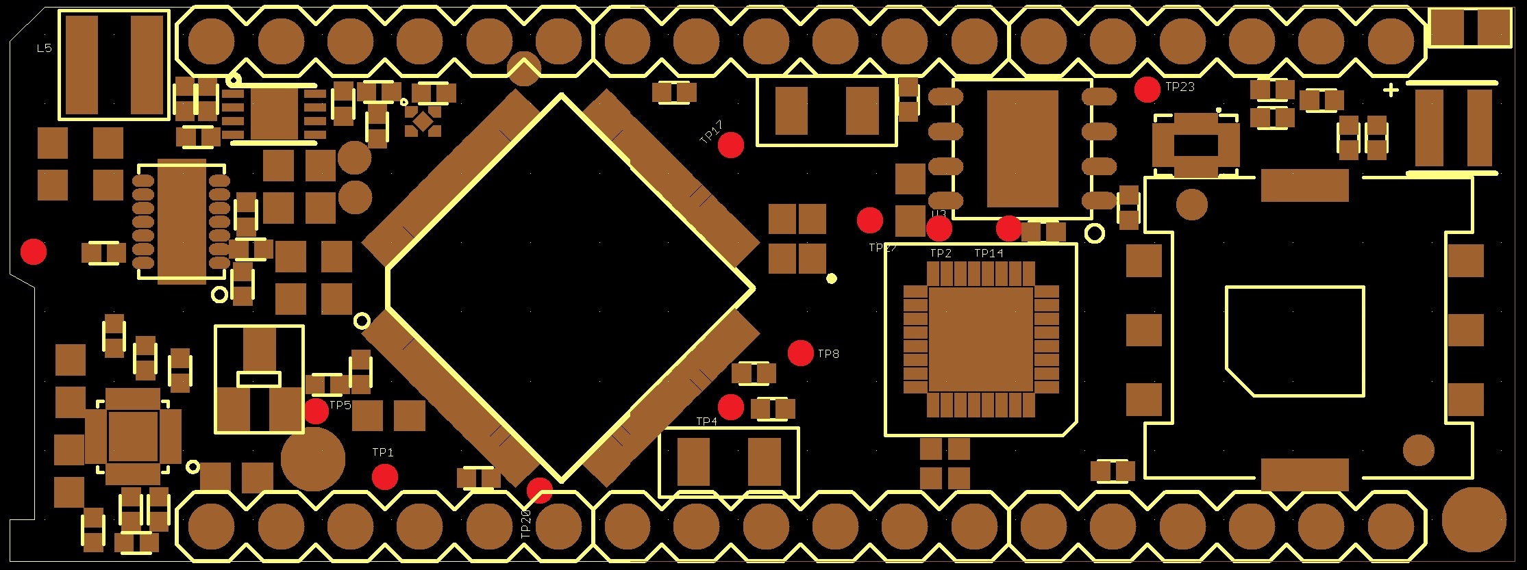
Test points are red. If you zoom in you can see the labels.
TP1 = USB_5V
TP2 = SWDIO System - label hidden under part
TP4 = User SWDCLK
TP5 = USB_IN (‘inside’ fuse from TP1)
TP8 = SWDIO User
TP13 = VBATT - not labelled on the overlay - this is the far left in the image below
TP14 = SWDCLK System - label hidden under part
TP17 = User Reset
TP20 = Ground - label hidden under part
TP23 = uBLOX-to-System TX
TP27 = System Reset - label partially hidden under part