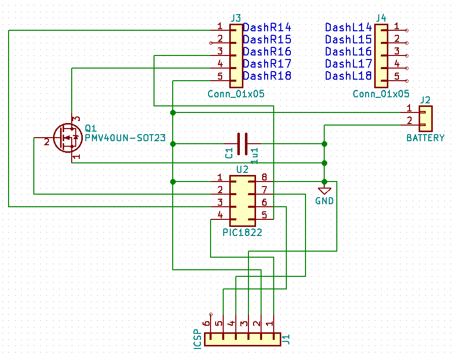
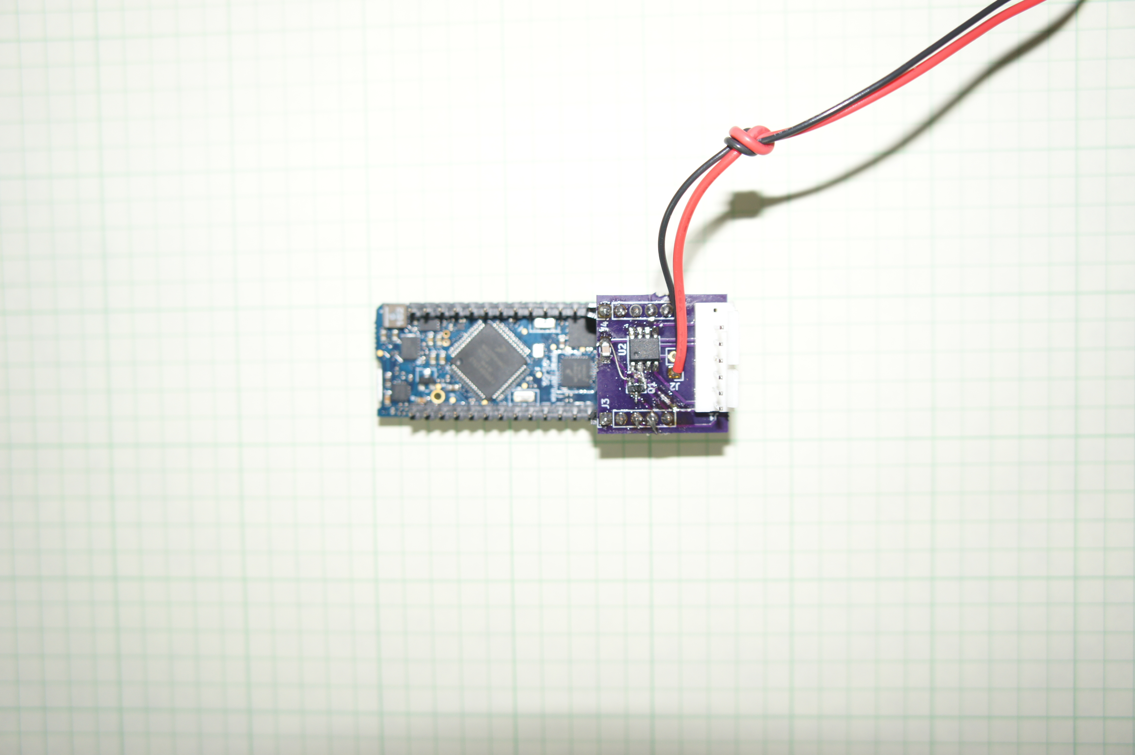
In the application I develop for, I needed standby power lower than I could get the Dash do for me. I only need the dash on maybe once a day or week, or whenever enough energy has been harvested to send a data point. I made a little add on board with a PIC and a FET. The PIC then turns on the Dash after the prolonged sleep. This way, it uses about 500 nA at 2.5V and 700 nA at 3.3V - exactly where the specs for the PIC say it should be.
This sounds really interesting. We’d love to take a look.
Also the Dash 1.2 coming out soon will get much lower power consumption numbers in sleep mode than the previous version. It’s not going to get as low as what you’re able to do with your board, but might help a bit with your application.
I did mess up the pin assignments for the FET when going from schematic to layout, so I had to do some cutting and jumpering …
Here the sample code for the PIC:
// CONFIG1
#pragma config FOSC = INTOSC    // Oscillator Selection (INTOSC oscillator: I/O function on CLKIN pin)
#pragma config WDTE = ON        // Watchdog Timer Enable (WDT enabled)
#pragma config PWRTE = OFF      // Power-up Timer Enable (PWRT disabled)
#pragma config MCLRE = ON       // MCLR Pin Function Select (MCLR/VPP pin function is MCLR)
#pragma config CP = OFF         // Flash Program Memory Code Protection (Program memory code protection is disabled)
#pragma config CPD = OFF        // Data Memory Code Protection (Data memory code protection is disabled)
#pragma config BOREN = ON       // Brown-out Reset Enable (Brown-out Reset enabled)
#pragma config CLKOUTEN = OFF   // Clock Out Enable (CLKOUT function is disabled. I/O or oscillator function on the CLKOUT pin)
#pragma config IESO = ON        // Internal/External Switchover (Internal/External Switchover mode is enabled)
#pragma config FCMEN = ON       // Fail-Safe Clock Monitor Enable (Fail-Safe Clock Monitor is enabled)

// CONFIG2
#pragma config WRT = OFF        // Flash Memory Self-Write Protection (Write protection off)
#pragma config PLLEN = OFF      // PLL Enable (4x PLL disabled)
#pragma config STVREN = ON      // Stack Overflow/Underflow Reset Enable (Stack Overflow or Underflow will cause a Reset)
#pragma config BORV = LO        // Brown-out Reset Voltage Selection (Brown-out Reset Voltage (Vbor), low trip point selected.)
#pragma config LVP = ON         // Low-Voltage Programming Enable (Low-voltage programming enabled)


#include <xc.h>

void main(void)
{

        OSCCONbits.IRCF = 0b0000;              // set clock to 32khz
        WDTCONbits.WDTPS = 0b10000;            // watchdog timer to about 64s to switch state
        // generic reset into known state
        TRISA = 0xFF;                          // set all digital I/O to inputs
        ANSELA = 0x00;                         // disable all analog ports;

        // pin specific configuration
        PORTAbits.RA5 = 1;                     // Start in off state
        TRISAbits.TRISA5 = 0;                  // set mosfet control pin to output

        while (1)                              // forever
        {
            SLEEP();                            // sleep until watchdog times out
            PORTAbits.RA5 = !PORTAbits.RA5;     // switch pin state
        }
}
I should point out that we messed up the pin descriptions a bit on the schematics. DashR18, as we call it is really DashR01 (Battery +). DashR17 is really DashR02 (Gnd). To add insult to injury, I plugged the add-on board in the wrong way before taking the example picture (but did not power it on).
If someone needs it let me know and I can go back and fix the pictures, but I think the crowd here gets how it’s supposed to look…