Let’s say I have a sensor that likes to communicate over TTL. (i.e. many maxbotix ultrasonic sensors). Let’s say that I want to address it from the Konekt Dash Pro Beta. I can’t seem to find documentation that shows me how to wire it up and communicate. Is it as simple as Serial1.xxx or something different. How many UARTs and all the other ports are there? Is every pin a GPIO (both analog and digital?)?
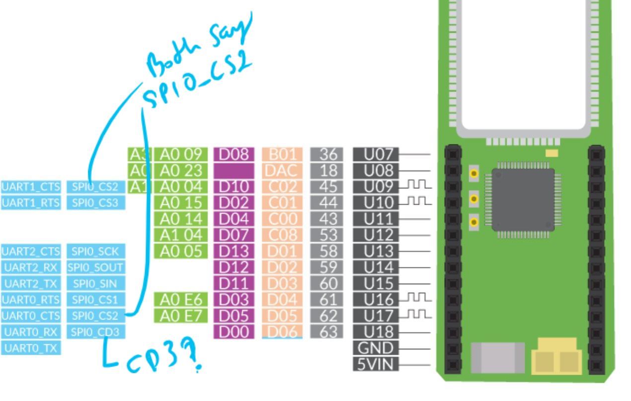
I see that there is an i2c, three uarts (with flow control?), an SPI (with 4 chip select (aka slave select) pins although two are labeled the same, a cd pin, a sck (clock), an sout (Mosi?), an sin (miso?). There are also a bunch of analog and digital io.
What is the cd pin for? Can we comm with 3 or 4 devices over Spi? Are the uarts TTL 3.3 v or rs232 capable out of the box? I’m just not used to seeing dedicated rts and cts pins. Are any of the uarts tied up in communicating over the USB cable or communicating with the modem. In fact, are any of these pins overlapping with modem io?
Can you point me to where you see the CD pin? I just looked over both of the pin diagrams, but I didn’t see it. Maybe a fourth cup of coffee will help.
The firmware supports 4 hardware select pins for SPI, but it is really easy to use any other GPIO to select additional devices. If you’re clever, you can use logic gates to expand the number of target devices to a very high number. Additionally, you can use a SPI based logic extender to control even more devices.
SOUT is indeed MOSI and SIN is indeed MISO. I prefer the full nomenclature, but decided to match what’s in the datasheet for the chip.
All pins on the chip are +3.3V logic level. The pins are not rated for RS232 voltage levels. You would need additional circuitry to step up the voltage. The flow control is on many microcontrollers, but on dev boards, often aren’t exposed to the user.
One of the UARTs is tied up with communicating with the system IC, which talks to the modem. The UART on the chip is connected to two sets of pins. It’s possible to switch it from one set of pins and move it to another. We currently don’t support that feature, but it’s possible. The same is true for I2C0, except that is only used when the system is in bootloader mode. We’re waiting on certification to release the schematics, but then you’ll be able to see everything for yourself.
Aha! I don’t know if I would have found that without a text search. Thank you! CD3 == CS3. There are two CS3 pins and two CS2 pins. Freescale has multiple pins for many of the IC’s functions. You can pick whichever one you want to use. I’m not sure how that’s going to be handled in the API. They don’t let me out of my cage :).
Am I correct that I can program the Dash to be an I2C slave receiver device using the Arduino IDE Wire library? I can then take the received data and send it to Konekt Cloud?
The Arduino Slave Receiver code seems very straight forward. It’s kinda like “it can’t be this easy, what am I missing?”