There is probably a simple answer to this, but I want to ask before I brick another Dash. I am wondering the correct way to wire in a voltage divider when powering the Dash via the VIN pin vs. battery or USB?
I am powering the DASH via a 6V battery pack wired to VIN and GND pins. This powers the board and everything works fine. What I want to do however is monitor the state of the battery pack. To do this I need to build a voltage divider. I have the divider circuit working on its own, but when I incorporated the Dash it bricked the Dash I was using.
My questions are?
Do I wire the second resistor to battery -? It seems this would cause a constant draw on the battery through the resistors speeding up the drain
Is there a way to turn the divider on only when needed using Dash pins or does that require an external component?
How much voltage is your divider making. 3V? What size resistors are you using, 1 Meg or 1K? Are you over drawing power or putting to much voltage into an IO pin.
I will be doing the same and my plan is, I have 12V battery, regulated to 5 V, which could go as high as 14.4 V since it is a car battery on a solar charger. I will use 6 megohms of drop. The divider will be made up of 5 megohms and 1 megohm. 5 will tie to the battery, then tied to 1 megohm which will tie to ground. The voltage to measure the battery will be pulled from the connection of the 5 and 1. These will all be 1% resistors, don’t use 5%, you might as well just guess. At 18 Volts, the extreme, I will see 3 V, at 12V I will see 2V. I will run this line into an A/D and set that to either 12 or 16 bits.
You could use a FET to turn on the voltage divide on and off via power in and using an IO line, there should be all kind of examples out there, but I would think if you go with megohms you are pulling micro-amps… The FET will also have voltage drop across the drain 0.2 volts depending on the chemistry.
I had not hooked it up to an input pin yet because I was only testing with a voltmeter first. R1 is a 5k and R2 is a 2k resistor. This drops my voltage from 5.95 to 1.67 currently. The only thing I had wired was the Dash Battery + to VIN and the top of the divider. Battery - to GND and the bottom of the Divider.
Dash died and makes a very faint squealing noise when power is connected now. If I leave it connected to power (without the divider) it actually gets pretty warm to the touch.
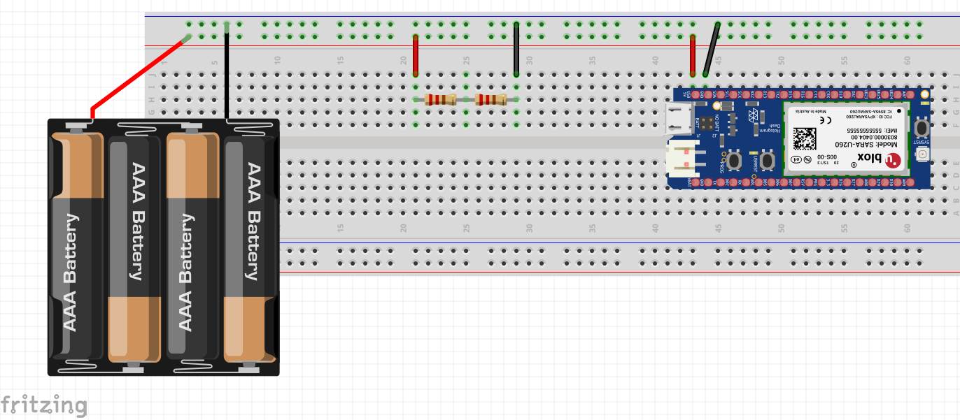
Here is basically what I was going to do wiring wise, but using a Dash instead of an Arduino of course. I never got around to wiring out the A0 port because my first Dash died just wiring up power.
I would definitely go with a higher resistance value, something akin to what @mtstarr is doing. Something in the Megaohm range will lower draw on the battery. Using something in the E6 series resistor set like a 1M and a 2.2M should divide down fine:
Putting those two in line will result in roughly 1/3 your input voltage at the A0 pin. Assuming you don’t expect to see your voltage above 6V, you should be fine.
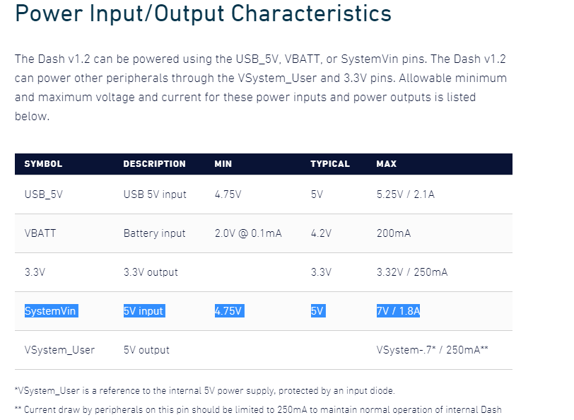
I’m sure you’ve already looked at our absolute maxes listed for the dash:
One other suggestion since you are “battery” operated. Why not just use a LiPo and connect it to the LiPo charger. Have two of them, when one is drained, replace it with the charged one. I assume since you are talking about 6V you may be using 4 1.5v cells…
Long story, but in a nutshell I don’t believe the Dash is a suitable platform, in it’s purchased form, for what I am doing. The sensors I am deploying have a designed minimum life of 10 years on battery and we have some that have lasted over 20. I am experimenting with the Dash to see if I like the platform and to see what kind of life can be achieved on battery. Once in the field going and replacing batteries regularly wouldn’t be an option.
I think a lot of this has gotten away from my initial concern though. I don’t understand why I would have bricked the Dash by just creating the voltage. I hadn’t connected it to an analog read port yet so it couldn’t of been an over voltage condition on the analog pin. I just don’t want to brick another one if there is something in the design of the circuit or the Dash that would have caused this.
After that most of what I am doing is learning about the platform.
At these kinds of battery requirements (10 years is really tough with a normal set of batteries), it’s unlikely cellular at all will be the right solution for your application (without a recharging component like like a solar cell).
I definitely think you’re taking the right tact to try it out first and I’m a bit concerned you bricked a dash. Could you give more context on what happened during that testing?
Back to your original problem and your 2nd question. By not connecting the “bottom” resistor to a common ground, ie battery and ground on the Dash you were applying the full battery voltage to the ADC pin on the Dash. However, your 5K resistor would allow about 9V / 5K or roughly 2mA to flow into the input pin. I believe clamp diodes, on the silicon, to supply and ground are common input protection devices. You would need to find out how much current these could handle.
Also, as suggested using high value divider resistors like 5 and 1M Ohm will not result in the calculated voltage at the output when you load it with a digital voltmeter or the ADC pin on the Dash. However, you can compensate for this in subsequent calculations.
I hadn’t connected it to an analog read port yet so it couldn’t of been an over voltage condition on the analog pin.
Then your divider wasn’t the problem!
By “analog read port”, do you mean a GPIO or a specific ADC input?
@ Chris, Our current 3G radio averages 13-16 years based on accelerated life testing at temp ranges between -40c and 70c. It uses a 8 cell battery AA lithium Ion battery pack but requires a minimum of 9 volts for full operation. The new radio will only use 4 cells, but will also require far less power to operate.
As far as what I did when the Dash failed. I had the Dash installed on a solderless breadboard and had the Batt- tied to the GND pin on the Dash. Batt+ was disconnected while I built the voltage divider circuit on an adjacent breadboard. I tied the bottomleg of R2 to Batt- with the GND pin of the Dash. I then tied the top log of R1 to Batt+ and Dash VIN pin. This is the point the Dash failed. I had not tied a Vout from the divider to anything yet. A Multimeter test of the bridge between R1 and R2 showed an output voltage of approximately 1.6volts.
I will try to put together a drawing in fritzing or something to show what was connected and how shortly. Maybe it was a fluke that the Dash died on me at the same moment.
My apologies, I assumed this was a standard set of AAs. Agree that the new radio will help with extending lifespan and if you end up integrating the 4G modules on the way, that will extend even more (can evaluate on 3G and easily swap to 4G when they’re sold)
No problem Chris, I didn’t specify early. Here is what I had wired when I plugged the Batt + back into the breadboard (Ignore battery type in the drawing)
So, you are putting 6 V into a 5V USB power pin. So, you may have bricked your Dash by putting 6 Volts into it, not really sure but I believe that pin is not rated for that voltage. You could drop down to 4.5 Volts and be better off, drop a cell out.
Does the program button flash when pressed?
No, other than a faint squeaking noise it does nothing. According to the data sheet that is a 5v pin with a max input of 7v. My pack is outputting 6 so I should be fine. My board is a Dash 1.2 BTW. Not sure if I mentioned it earlier.
I didn’t want to drop a cell because then I am near the min voltage range and from what I have read it is very sensitive to under voltage conditions.
I believe you are talking about the "output 5V, that is why that pin has a max current load of 250 mA
SYMBOL
DESCRIPTION
MIN
TYPICAL
MAX
USB_5V
USB 5V input
4.75V
5V
5.25V / 2.1A
VBATT
Battery input
2.0V @ 0.1mA
4.2V
200mA
3.3V
3.3V output
3.3V
3.32V / 250mA
SystemVin
5V input
4.75V
5V
7V / 1.8A
VSystem_User
5V output
VSystem-.7* / 250mA**
The input 5V USB is rated at 5.25 Volts from what I have read. I think the pin you are referring too is located on the other side of the Dash at pin R01. Input is on L01, VSystem_User is 5V output, USB_5V is 5V input from what I see.
Yeah, it does look like that should have been ok if you were wired to Vin. Did you happen to have a DMM on that voltage at the time? (Not expecting you did, but I can hope)
Sorry, I see what you are connect to now. Did you ever plug this into a USB port? The USB port has a clipping diode attached, I assume 5 volt zener, then more or less becomes SystemVin. There is diode to prevent SystemVin to not drive voltage back onto the USB… Very odd that they limit the USB input voltage to 5.25, have a clipping diode and then tie that to the SystemVin… that can have higher voltage.
There is a fuse between TP1 and TP5 that you could check, but how you have described this you should not have had voltage across that…